Fitting the GOTEK FlashFloppy

In previous episodes of the Atari 520STFM refurbishment it was cleaned and recapped. This instalment sees installation of a replacement floppy drive. The GOTEK, sometimes known as FlashFloppy (really the name of the firmware it runs) is a drop-in replacement for a 3.5″ floppy disk drive which has several benefits:

  • It takes a FAT-formatted USB stick
  • The computer sees it as a normal floppy drive
  • It can serve a lot of 720K or 1.44MB disk images from a 16GB memory stick
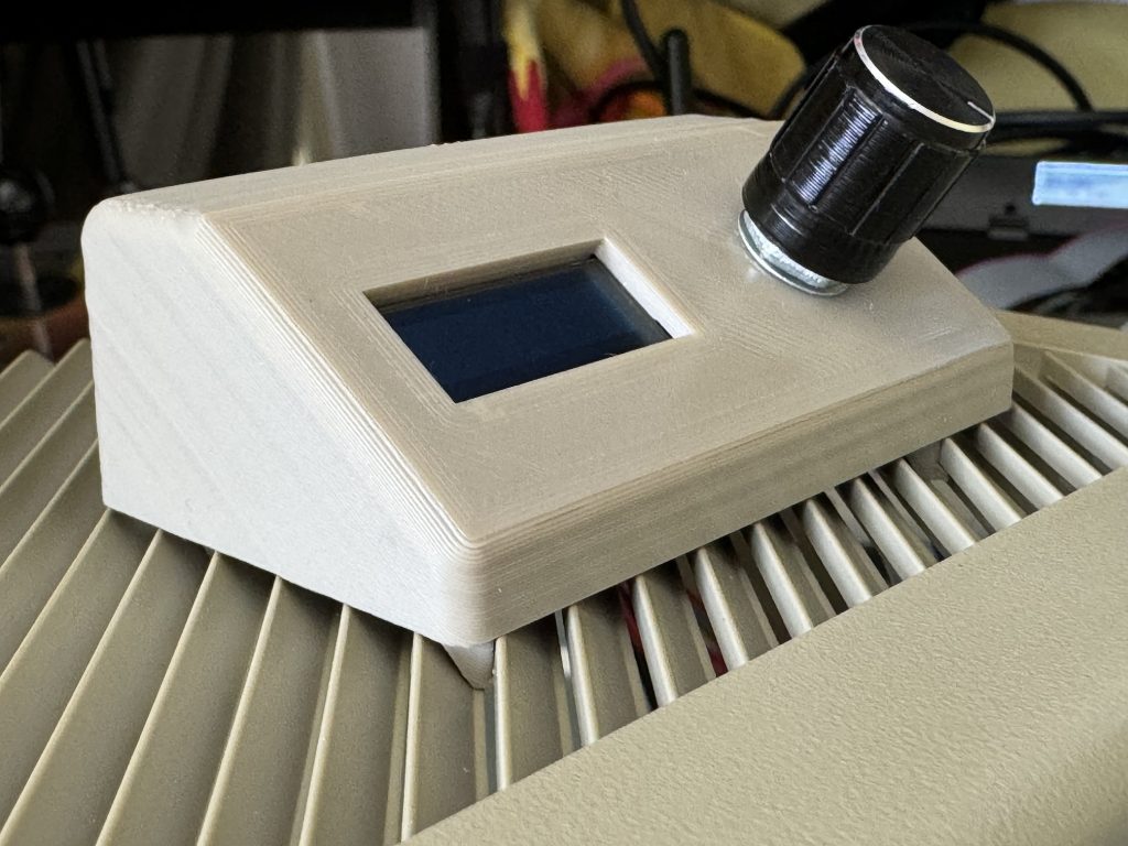
  • A tiny OLED screen makes disk selection pretty easy
  • It’s much faster than a floppy drive

The downsides are that you can no longer use your old floppy disks, and sadly it doesn’t make those nostalgia-inducing head-seek noises… at least my one doesn’t!

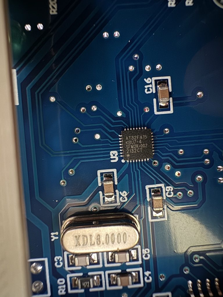
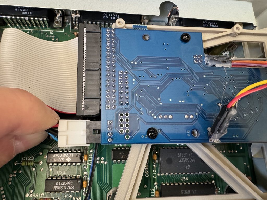
There are a couple of different GOTEK models, one old and one newer. The story goes that the price of the disk controller 10x’d so the makers changed it and the firmware wasn’t immediately compatible. My one, bought on fleabay UK, May 2024 has the newer chip.

ARTERY AT32F415 GOTEK disk controller

The drive chassis is approximately the same size as the floppy drive being removed, but this one was found to be fractionally shorter (approx 1cm) so the power cable would not reach.

Power cable fails to reach even at full-stretch

This was resolved by cutting approxiamtely 6cm of floppy power cable from a dead ATX power supply, and soldering four spare header pins left over from an ESP32 project.

A salvaged floppy power connector extension

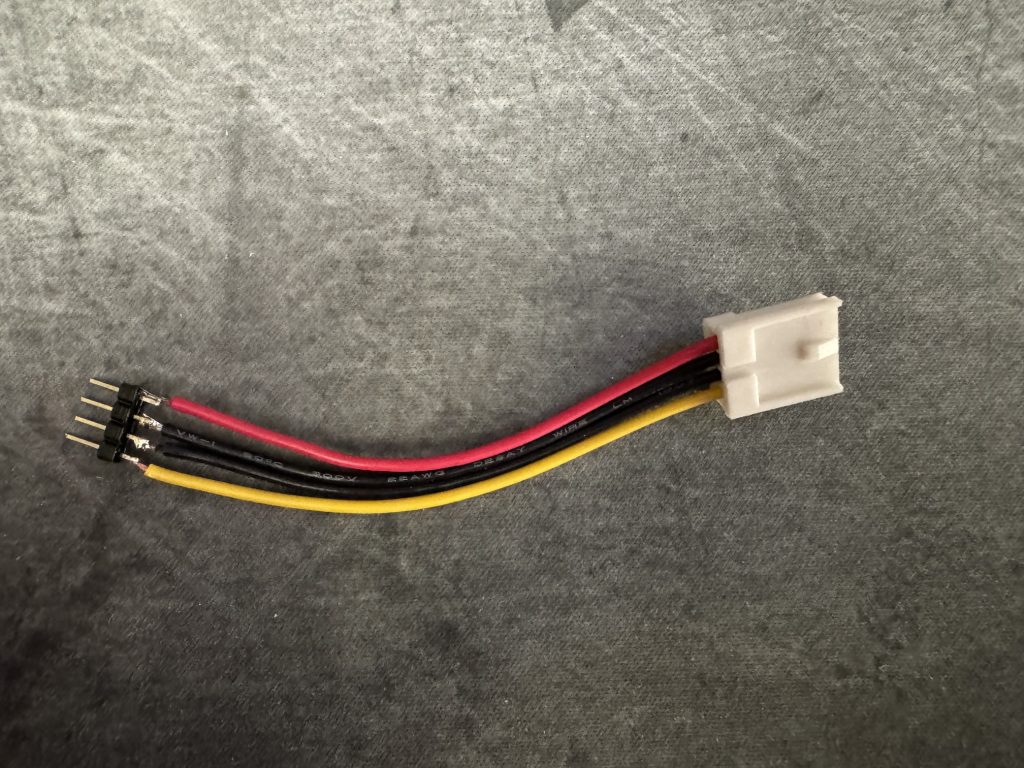
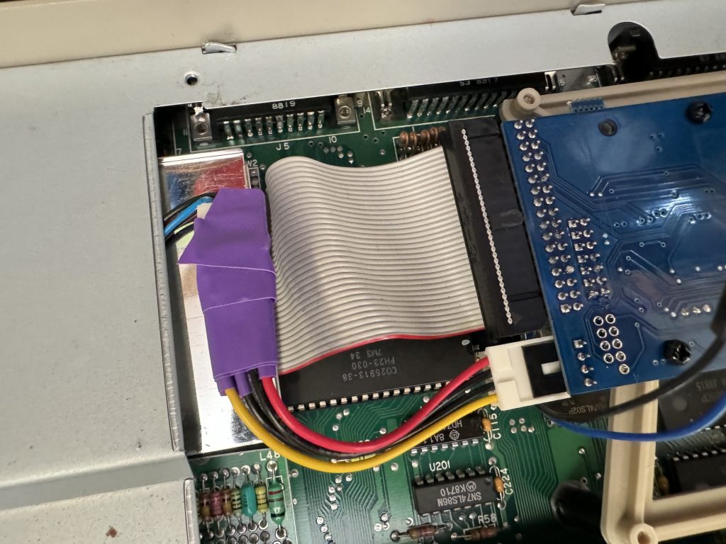
Naturally shrink-wrap sleeving is never available to hand so some fine purple electrical tape had to do. Hot glue would probably work quite well to secure the header pins as well.

Next come the flyleads for the GOTEK’s rotary controller and OLED display. Not all GOTEKs come with an external control/display – most seem to have the display built in and many only have up/down buttons, not a rotary control at all. Given the drive is on the side of the STFM, the standard display isn’t visible most of the time which isn’t very practical, so the external module seems much more useful. The display needs careful positioning as redoing it later is a PITA.

A small knife was used to very gently pry open one of the slots in the top of the case in order to position the display properly when clipped in. This is necessary because the connector blocks don’t fit through the slot without a little extra encouragement.

Gentle encouragement. Don’t crack the case!

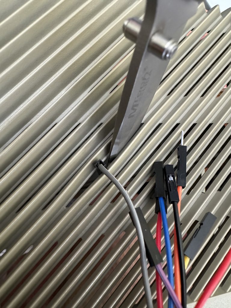
I took a moment to appreciate the colour-coding on the wires and the fact that the connectors on duplicate colours are alternately polarised meaning they cannot be connected incorrectly. That’s super helpful, but countered by the fact these one-pin blocks don’t make very solid mechanical contact, tending to fall out if you look at them wrong. Securing them using small spots of superglue seems to help.

Flyleads superglued into place

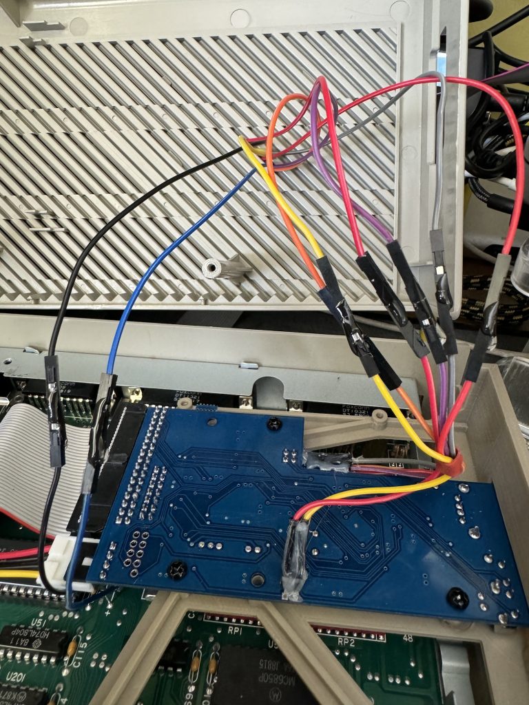
The excess wires are pushed through from the above and the controller/display module is positioned and clipped onto the top of the ST case such that the wires can’t be seen.

Rotary Controller and OLED breakout module

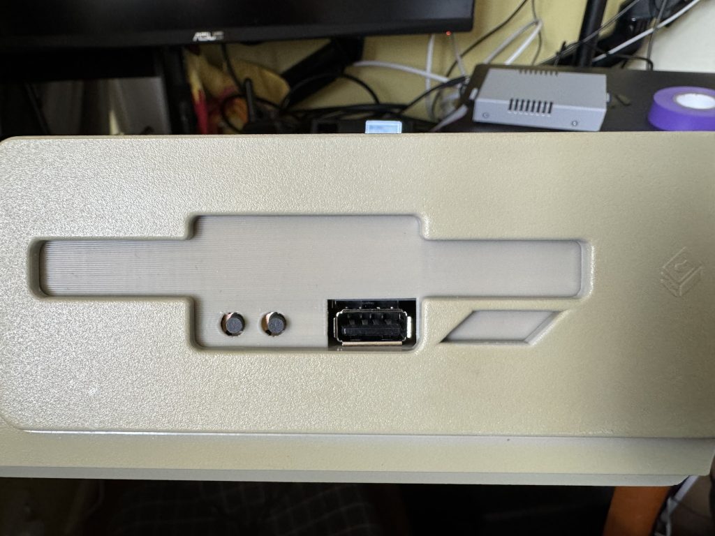
The drive itself has the USB socket very close to the old eject button surround moulding which interferes very slightly but in practice it doesn’t seem to affect USB connectivity. Unfortunately in this configuration, in order to allow the ribbon cable to reach, the drive is technically mounted upside-down.

Mounted GOTEK drive

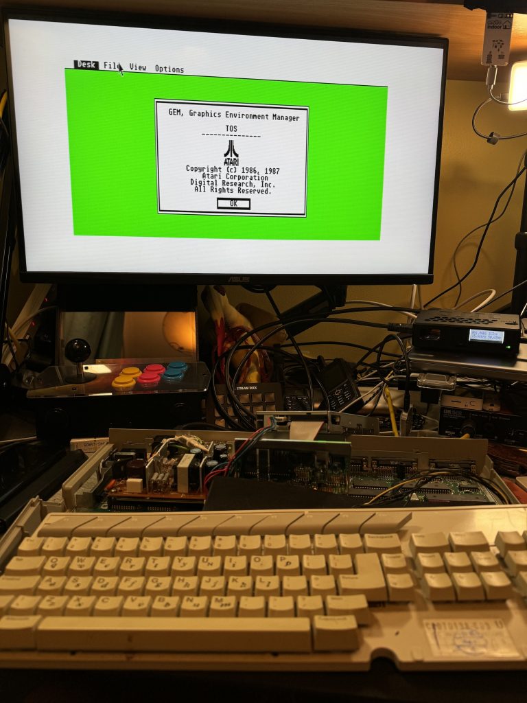
With everything closed back up it’s quite a smart-looking solution. Pretending to be a floppy drive doesn’t remove the quirks of using floppy disks but it does make them easier to deal with.

Atari 520STFM pictured with Ultrasatan SD virtual hard disk and GOTEK virtual floppy drive

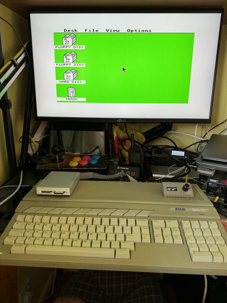
The firmware version shipped on the drive seems fine but it’s possible to flash updates using the FlashFloppy code and documentation here. All in all the GOTEK is pretty easy to fit aside from the extra power extension. I will almost certainly be fitting more in the future.

Atari STFM520 keyboard & case refurbishing

In part three of my ongoing nostalgiathon refurbishing an Atari STFM it’s time to clean up the keyboard and case.

The keyboard assembly before cleaning

Step one is to remove the keyboard from the chassis – very simple to remove the seven short screws from underneath to release the top-side of the case. The keyboard floats on the shielding and is connected via a delicate 8 pin (7 wired and one polarising blank) header connector. This keyboard wasn’t very grubby – I’ve definitely seen much worse. A little grime and some letraset lower case, plus the usual dust, fluff and crumbs in-between the keys.

Detail of using a keycap puller

Using a keycap puller makes very quick work of removing all the key caps without damaging the switches or support pillars. The Enter and Space keys also have metal stabilisation bars which can be carefully unclipped from the keyboard chassis. Be gentle with these bars – they’re attached to the keycaps using small plastic clips which are easy to bend and break.

Alphabet soup: keycaps taking a bath

All the keycaps soaked in warm water and washing up liquid. These were individually scrubbed with a soft washing up pad, which was enough to remove the grime and the letraset.

The keyboard assembly with all keycaps removed

The keyboard chassis with included light muck. This was wiped first with surface cleaning disinfectant wipes then with cotton-buds and isopropyl alcohol (IPA).

Rinsing the keycaps

After scrubbing, the water was changed and the key caps were rinsed.

Stabilisation bars and keycaps drying

Keycaps were left to dry on kitchen towel. Also visible are the stabilisation bars for Enter and Space on the left, and one of the stabilisation support clips on the bottom.

Oxicleaned top case

Whilst the key caps were being cleaned, advantage was taken of a pleasant sunny afternoon. The top case was liberally sprayed with oxyclean peroxide spray (similar to Retrobright) and left in the sun for several hours, respraying and rotating every half hour or so. This can also be wrapped in clingfilm to reduce or avoid respraying.

Reassembled keyboard – looking clean!

All the keycaps were replaced using a reference photo taken before disassembly. The stabiliser pivots also had a pinhead of lithium grease applied. I imagine this is only really to reduce squeaking.

Reassembled STFM

Seeing everything reassembled in the case is very satisfying. The top case only suffered slight yellowing which has mostly cleared up now. I’ll have to try it again soon with my other STFM which is much worse.

Installing the Exxos 4MB RAM Atari STFM expansion

In the unlikely event you read my earlier post on recapping the Atari STFM power supply, you’ll know I recently acquired a good example of a mid-late revision Atari 520STFM. Now its PSU has been recapped and cleaned up, it’s time to have a crack at upgrading it from half a megabyte of RAM to 4MB, the most it can take in stock config.

There are several ways to perform this upgrade, from the difficult but reliable desolder all the current RAM chips, source and buy new compatible ones and resolder them, to piggybacking daughterboards of various types, heavily dependent on the motherboard revision in question.

C103253 rev.1 Atari STFM motherboard before expansion

My motherboard is a C103253 rev.1, as pictured so for this upgrade I opted for the Exxos “The LaST Upgrade” MMU piggyback with a stacking board which sits on the shifter chip and connects with a ribbon cable.

Opening up the shielding (centre of image above) revealed a socketed shifter. Apparently this isn’t always the case but it’ll do for me. The shifter chip can be gently pried out of its socket with a thin blade, then inserted into the shifter daughterboard, which I bought fully assembled. This can then be inserted back into the shifter socket, and that part is complete. Next time I do this I’ll consider buying the kit to construct, as it’s not a very complicated assembly.

The shielding doesn’t fit back over the stacked shifter now, which is flagged as an outcome in the documentation. I didn’t want to completely remove the shielding so I opted to bend it over backwards over the video modulator. It just fits now under the main case shielding when it goes back on, which is great, but it does now interfere with the floppy ribbon cable in particular. This makes it awkward to put the original floppy drive back in but might be sufficient with a GoTek as they look a little shorter than the original drive. I don’t have one to test-fit yet so I might need to revisit this shield later.

Next on to the MMU piggyback. The pitch of these pins is smaller and they look very delicate compared to the pins on the shifter for example. This daughterboard sits directly on top of the MMU – its retaining clip needs to be removed – and requires a disconcerting amount of pressure to seat it fully in the socket, as its pins are jammed in next to the socket pins. I chose to pull the motherboard out of the bottom case, seat the daughterboard and carefully push down onto it, and a desk using the palm of my hand and my weight. It felt extremely uncomfortable as I’ve never had to use that much force to seat a chip.

Lastly the old RAM still soldered onto the motherboard either needs to be removed, or disconnected. Doing the latter is much less work and can be reversed later if necessary. The 68ohm resistors R59, R60 and R61 need lifting to 5V. On this motherboard this means desoldering and pulling the right-hand-side legs, closest to the MMU then adding a jumper wire over to the +ve leg of the 4700µF capacitor adjacent on the motherboard.

Use solid core wire, not like I did here

4MB Atari STFM booted to GEM desktop

The result is a 4MB STFM (woowoo!) which boots to desktop and as yet has no way to run software because the flopy drive is dead and I haven’t formatted any SD cards for the ultrasatan yet (and will that even work with TOS 1.02?). Haha.

All parts were sourced from Exxos, with advice from the Atari ST and STe users FB group.

Installing the Exxos Atari ST PSU recap kit

I recently acquired a classic 16bit machine from my childhood in the form of a Motorola 68000-powered Atari 520STFM. Whilst it’s a later motherboard revision – C103253 REV.1 – it’s still a low-spec model with only 512MB RAM. The “F” in STFM is for the included 3.5″ floppy disk drive with the “M” being for the built-in TV modulator.

My hope is to upgrade this machine to the maximum of 4MB RAM and see which other add-ons (e.g. GoTek USB-stick floppy drive replacement; ultrasatan SD-card virtual hard drive; TOS upgrades; PiStorm accelerator) will best modernise the experience.

Atari 520STFM motherboard C103253 Rev.1

But first things first, I know enough to not turn it on in excitement – the most common fault with these older machines is failing electrolytic capacitors as the paste in them dries out, particularly in hotter environments like power supplies, so let’s have a look at the PSU… This model is a common Mitsumi SR98. We’re looking for bulging capacitor packages like this one.

A bulging electrolytic capacitor

The Exxos PSU refurbishment kit includes a replacement set of capacitors, a couple of replacement resistors and modern, more-efficient rectifier and low voltage schottky diode. This results in improved stability, improved ripple and lower temperatures. It’s also well within my soldering abilities!

The Exxos refurbishment kit, as it comes
Mitsumi SR98 PSU as it came, with replacement targets highlighted.

The fiddliest part is easily the rectifier as the new one is significantly larger and a different shape, but once it’s all done it looks something like the image below. A quick visual inspection underneath for bridged tracks and stray solder, maybe a quick clean with isopropanol and a toothbrush, and it’s ready to go.

The refurbished SR98 PSU, top side
Refurbished SR98 PSU, bottom side

The refurbished PSU is refitted carefully back into the case and reconnected to the low voltage header on the motherboard. Various parts of the PSU are mains live when turned on (danger of death!), so extreme care needs to be taken if the whole case isn’t reassembled. Also note that this PSU likes to be loaded – i.e. not to be run bare, so don’t turn it on without plugging something in (ideally a cheap bulb, rather than an expensive motherboard).

Using a multimeter I measured the voltage across the large 4700µF capacitor and trimmed VR201 down slightly to bring the voltage closer to 5.00V.

Now flipping the power switch results in a little green desktop and no magic smoke!

Little Green Desktop

This booted without a keyboard, mouse or floppy drive. I used an RGB SCART cable to an OSSC scan doubler (middle right), then HDMI to a regular modern monitor. The image in both low and medium resolutions is crisp and clear with very little hint of instability.

Next steps: cleaning the keyboard, retrobrighting the case, upgrading the TOS ROMS, fitting the 4MB RAM upgrade, Gotek and ultrasatan drives.

All the information I used for this PSU refurbishment was from the Exxos Forum.