In the unlikely event you read my earlier post on recapping the Atari STFM power supply, you’ll know I recently acquired a good example of a mid-late revision Atari 520STFM. Now its PSU has been recapped and cleaned up, it’s time to have a crack at upgrading it from half a megabyte of RAM to 4MB, the most it can take in stock config.
There are several ways to perform this upgrade, from the difficult but reliable desolder all the current RAM chips, source and buy new compatible ones and resolder them, to piggybacking daughterboards of various types, heavily dependent on the motherboard revision in question.

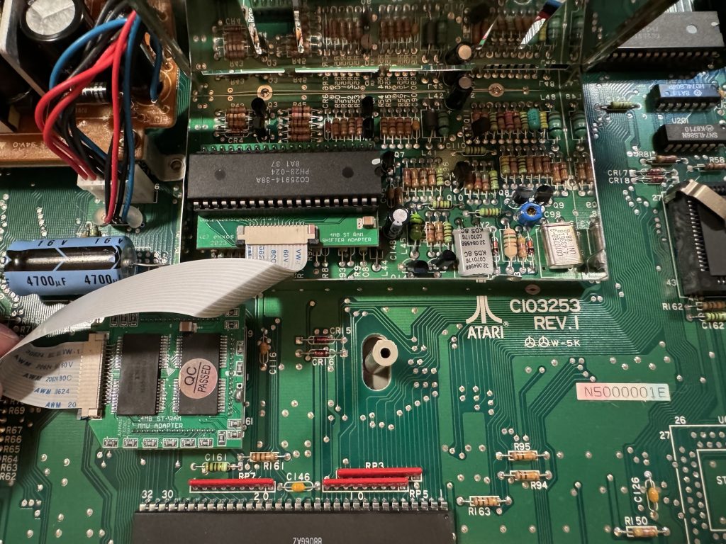
My motherboard is a C103253 rev.1, as pictured so for this upgrade I opted for the Exxos “The LaST Upgrade” MMU piggyback with a stacking board which sits on the shifter chip and connects with a ribbon cable.
Opening up the shielding (centre of image above) revealed a socketed shifter. Apparently this isn’t always the case but it’ll do for me. The shifter chip can be gently pried out of its socket with a thin blade, then inserted into the shifter daughterboard, which I bought fully assembled. This can then be inserted back into the shifter socket, and that part is complete. Next time I do this I’ll consider buying the kit to construct, as it’s not a very complicated assembly.
The shielding doesn’t fit back over the stacked shifter now, which is flagged as an outcome in the documentation. I didn’t want to completely remove the shielding so I opted to bend it over backwards over the video modulator. It just fits now under the main case shielding when it goes back on, which is great, but it does now interfere with the floppy ribbon cable in particular. This makes it awkward to put the original floppy drive back in but might be sufficient with a GoTek as they look a little shorter than the original drive. I don’t have one to test-fit yet so I might need to revisit this shield later.
Next on to the MMU piggyback. The pitch of these pins is smaller and they look very delicate compared to the pins on the shifter for example. This daughterboard sits directly on top of the MMU – its retaining clip needs to be removed – and requires a disconcerting amount of pressure to seat it fully in the socket, as its pins are jammed in next to the socket pins. I chose to pull the motherboard out of the bottom case, seat the daughterboard and carefully push down onto it, and a desk using the palm of my hand and my weight. It felt extremely uncomfortable as I’ve never had to use that much force to seat a chip.
Lastly the old RAM still soldered onto the motherboard either needs to be removed, or disconnected. Doing the latter is much less work and can be reversed later if necessary. The 68ohm resistors R59, R60 and R61 need lifting to 5V. On this motherboard this means desoldering and pulling the right-hand-side legs, closest to the MMU then adding a jumper wire over to the +ve leg of the 4700µF capacitor adjacent on the motherboard.

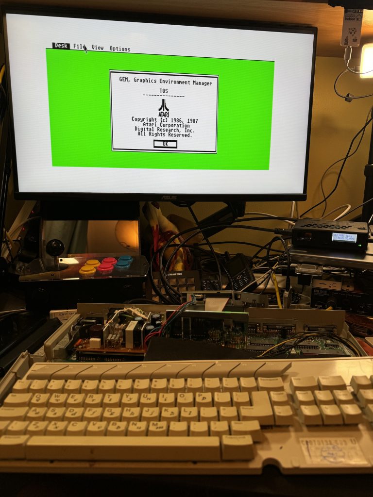
The result is a 4MB STFM (woowoo!) which boots to desktop and as yet has no way to run software because the flopy drive is dead and I haven’t formatted any SD cards for the ultrasatan yet (and will that even work with TOS 1.02?). Haha.
All parts were sourced from Exxos, with advice from the Atari ST and STe users FB group.