Why do I run a homelab?

It used to be tidier, honest. NTP server, PDU, patch panel, UDM Pro, PoE switch, proxmox servers, fans, NAS, AI PC and shonky cooling. UPS not pictured. The small yellow boxes are wideband RF preamps.

So… I’m a geek. No hiding from it. Gone are the days when being a geek mostly meant having the shit beaten out of you in the playground. These days geeks rule the world. So, I’m a geek. I love playing with computers. I love playing with radio. I love playing with electronics. I’m a hacker, in the original sense of the word. That is to say I derive enjoyment from making tools, products, systems do things they weren’t designed to do.

Why? It’s educational, it’s fun, it’s frustrating enough to (sometimes, not always) give a great sense of satisfaction and achievement after solving a problem which has been bugging me for sometimes weeks. It’s inspiring, to learn new tools, to figure out what they’re good at, and what they’re bad at, and to use them to solve problems, more often than not, of my own making.

So I run a VPS (using Linode). I’ve run that VPS since 2008, running every Ubuntu release from 8.04 to 24.04. There I host my own MTA, my own web server for multiple domains, I host websites, databases, dev environments and access endpoints for other people – it’s very handy – and at home I run a homelab.

What’s a homelab? It’s intended for experimentation and learning systems, tools, applications, configurations and all that. All things you can and should learn on your day job, but without the knowledge from first-principles you’ll unlikely find that job int he first place.

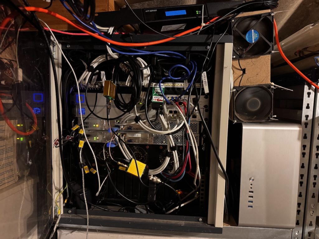
Well perhaps my setup isn’t quite a homelab. A large proportion isn’t particularly experimental. A lot of the services I run at home keep me cosplaying as a sysadmin, that’s for sure. If you’re going to do it, you have to do it properly, so here goes:

  • I run a highly-available cluster using proxmox
  • I run highly-available DNS using unbound which provides some Ad-blocking controls
  • I run a Ubiquiti unifi controller and network built around a UDM Pro – easily one of my favourite pieces of networking infrastructure
  • I run failover internet lines (Gigaclear FTTH 1Gbps + Talktalk ADSL 70Mbps)
  • I run multiple VLANs for LAN, Guest, IoT, Surveillance
  • I run a Step-CA certificate authority and use it for SSL certs for all internal services.
  • I run a Squid caching-proxy server to (slightly) reduce internet traffic and add further Ad-blocking controls.
  • I run a Lancache for game library caching
  • I run CCTV/NVR using Frigate
  • I run remote access using Tailscale
  • I run Ollama, edge-tts
  • I run Gitlab source control
  • I run n8n for workflow automation, news aggregation, agentic AI, and I’m exploring what else I can do with this.
  • I run home assistant for home automation
  • I run Observium for monitoring
  • I run Wazuh for XDR/SIEM
  • I run a reprepro server for deb package distribution
  • I run a docker registry for docker image distribution (yes I suppose I could use gitlab for this, but I like keeping it separate)
  • I run another internal, satellite postfix MTA which hands off to the VPS
  • I run a CUPS airprint spooler – less useful these days than it used to be when half the clients didn’t have the correct printer drivers
  • I run nextcloud for DIY cloud storage & sharing
  • I run Calibre-web for book/magazine/academic paper library
  • I run Plex for home media library, sharing with iPads and Amazon Firesticks
  • I’ve just this week installed a local Penpot server to see if it’s useful enough to use instead of Figma
  • I run a weewx weather-station
  • I run a satellite-weather SDR receiver, driven by “predict
  • I run an ADSB receiver driven by flightaware-1090
  • Other devices on the network which aren’t directly in the homelab include things like a trusty DS1819+ Synology, HD Homerun, hamclock, Pi-Star, Echolink node, Allstarlink node, experimental Packet node, NTP server, enviro RPi Pico monitors and a raintrackr, not to mention the family laptops, PCs, TVs, iPads, smartphones, smart plugs, smart lights, NVR cameras, Echos, Google Homes and all that other junk.
  • Mostly kept online by an old Dell UPS cast-off from work – PoE Wireless APs to the rescue!

I’m sure I’ve forgotten a bunch of things, but that’s the gist of it. I do not like paying for subscription services if I can avoid it. I’m sure my response of installing everything and running it at home is pretty atypical, but I like being (mostly) in control of my own services.

The experimental side of my homelab actually comes in a different form – that’s the portable kit I take to field events (scouting and similar). That comes with a whole other set of hardware for servicing a mobile LAN but still having local fast file storage, server redundancy, backhaul links, VPN, caching, DNS and similar. That’s for another post.

There was a time when I would have STRONGLY preferred hiring developers and engineers into my teams who do this sort of stuff in their spare time. I’ve interviewed and hired a lot of developers and engineers into my teams over the last quarter century and I often look for the tinkerer in the candidate. I want them to be excited not only about the company or team but about technology itself.

To be honest I still think like that, apparently because I’m some sort of tech dinosaur. It seems learning and experimentation in one’s spare time has fallen out of fashion for a huge proportion of people. I don’t expect to see a stupid amount of github commit history – though that’s often encouraging to see. I know that if you’re working for most companies, that intellectual property is private, commercial, top secret, verboten, and certainly isn’t going on a public repository for a someone else’s AI training.

I get it – I was never paid for solving massive, difficult, long-standing system engineering and architecture problems for work in my sleep, which happened on many occasions, as might be expected when working on groundbreaking novel science. It certainly used to piss me off that what little recognition was received was never really proportional to the amount of effort put in either in work, or in overtime, or in own-time. I need to get over that – that’s a very much a “me” problem. In the meantime I need a bigger server cab.

What should I run on my homelab? What do you run on yours?

A photo/calendar frame with the Inky Impression 7.3″

I’ve been excited by e-ink displays for a long while. I leapt on the original, gorgeous reMarkable tablet as soon as it came out and have been a regular user and advocate ever since. I would dearly love to have one or two of these enormous 42″ e-ink art poster displays on the wall, but that’s for another day.

I’ve also been a long-time customer of Pimoroni and was aware of their range of nifty Inky displays. I recently came across this neat project by @mimireyburn and managed to pick up a 7.3″ Inky Impression after it being on back-order for only a week or two.

The Inky Impression 7.3″ with protective film and screen reflection
The Inky Impression 7.3″ rear with mounted Raspberry Pi Zero 2W

After flashing RPi OS on a clean card for the Pi Zero 2W, downloading the project, setting up Python, compilers, virtualenvs, prerequisites, etc. I was presented with a complete failure of the underlying driver and inky library to communicate with the display. This isn’t a fault of the inky-calendar project at all, may I reiterate, but unfortunately a very regular occurrence I’ve found when using many Pimoroni products.

Searching around I tried a few different things, including the usual modifications to boot parameters to enable the drivers/kernel modules and fiddling with permissions, users etc. but with no success. Now I’ve never deliberately pretended to be a Python programmer, nor do I particularly wish to be one, but I’m pretty good with debugging weird stuff and this was definitely presenting as a driver/library issue. Specifically some of the differences with the Inky Impression 7.3 seemed to be tripping things up, and it wasn’t a hole I fancied spelunking in today.

A little more digging highlighted a NodeJS package by @aeroniemi with working Impression 7.3″ display support. I definitely have masqueraded as a JavaScript programmer in the past so things were looking up. Some light Claude.AI vibing and I had two working scripts – one to fetch images from PicSum and another to replicate the calendar fetching+rendering, both from public iCal and authenticated Google Cal sources – awesome!

Some dremel butchery on the back panel of an old 7″ picture frame to fit around the sticky-out components on the back of the board and I was in business.

The rear of the photo frame with cut-outs for most of the components on the rear of the display
Extra clearance given to the left-most microUSB power socket on the Pi Zero 2W

Improvements

The only slight drawback with using this NodeJS library is that it only handles the image-display side of things – there’s no built-in support for the function buttons – something to revisit another day.

Another improvement would be to better-handle power – the main benefit of e-ink is that it doesn’t need power once the display has been set, and that’s not being utilised here at all – there’s a cronjob running on the Pi which displays the calendar before 10:00AM and photos after that, refreshing every half-hour.

*/30 6-10 * * * cd /home/frame/ ; node ical2png.js --calendar x --calendar y --google-calendar z --service-account KEY.json --view week ; node main.js --image calendar.png
*/30 10-23 * * * cd /home/frame/ ; node main.js --dither

Lastly, obviously, the display needs to load images from a folder rather than from the internet. That’s super-quick to do, and that’s this afternoon’s job. The calendar-rendering – fonts, sizes, colours etc. could do with a little more spit and polish too.

The code for this project can be found at https://github.com/rmp/inky-frame.

Fitting the GOTEK FlashFloppy

In previous episodes of the Atari 520STFM refurbishment it was cleaned and recapped. This instalment sees installation of a replacement floppy drive. The GOTEK, sometimes known as FlashFloppy (really the name of the firmware it runs) is a drop-in replacement for a 3.5″ floppy disk drive which has several benefits:

  • It takes a FAT-formatted USB stick
  • The computer sees it as a normal floppy drive
  • It can serve a lot of 720K or 1.44MB disk images from a 16GB memory stick
  • A tiny OLED screen makes disk selection pretty easy
  • It’s much faster than a floppy drive

The downsides are that you can no longer use your old floppy disks, and sadly it doesn’t make those nostalgia-inducing head-seek noises… at least my one doesn’t!

There are a couple of different GOTEK models, one old and one newer. The story goes that the price of the disk controller 10x’d so the makers changed it and the firmware wasn’t immediately compatible. My one, bought on fleabay UK, May 2024 has the newer chip.

ARTERY AT32F415 GOTEK disk controller

The drive chassis is approximately the same size as the floppy drive being removed, but this one was found to be fractionally shorter (approx 1cm) so the power cable would not reach.

Power cable fails to reach even at full-stretch

This was resolved by cutting approxiamtely 6cm of floppy power cable from a dead ATX power supply, and soldering four spare header pins left over from an ESP32 project.

A salvaged floppy power connector extension

Naturally shrink-wrap sleeving is never available to hand so some fine purple electrical tape had to do. Hot glue would probably work quite well to secure the header pins as well.

Next come the flyleads for the GOTEK’s rotary controller and OLED display. Not all GOTEKs come with an external control/display – most seem to have the display built in and many only have up/down buttons, not a rotary control at all. Given the drive is on the side of the STFM, the standard display isn’t visible most of the time which isn’t very practical, so the external module seems much more useful. The display needs careful positioning as redoing it later is a PITA.

A small knife was used to very gently pry open one of the slots in the top of the case in order to position the display properly when clipped in. This is necessary because the connector blocks don’t fit through the slot without a little extra encouragement.

Gentle encouragement. Don’t crack the case!

I took a moment to appreciate the colour-coding on the wires and the fact that the connectors on duplicate colours are alternately polarised meaning they cannot be connected incorrectly. That’s super helpful, but countered by the fact these one-pin blocks don’t make very solid mechanical contact, tending to fall out if you look at them wrong. Securing them using small spots of superglue seems to help.

Flyleads superglued into place

The excess wires are pushed through from the above and the controller/display module is positioned and clipped onto the top of the ST case such that the wires can’t be seen.

Rotary Controller and OLED breakout module

The drive itself has the USB socket very close to the old eject button surround moulding which interferes very slightly but in practice it doesn’t seem to affect USB connectivity. Unfortunately in this configuration, in order to allow the ribbon cable to reach, the drive is technically mounted upside-down.

Mounted GOTEK drive

With everything closed back up it’s quite a smart-looking solution. Pretending to be a floppy drive doesn’t remove the quirks of using floppy disks but it does make them easier to deal with.

Atari 520STFM pictured with Ultrasatan SD virtual hard disk and GOTEK virtual floppy drive

The firmware version shipped on the drive seems fine but it’s possible to flash updates using the FlashFloppy code and documentation here. All in all the GOTEK is pretty easy to fit aside from the extra power extension. I will almost certainly be fitting more in the future.

Atari STFM520 keyboard & case refurbishing

In part three of my ongoing nostalgiathon refurbishing an Atari STFM it’s time to clean up the keyboard and case.

The keyboard assembly before cleaning

Step one is to remove the keyboard from the chassis – very simple to remove the seven short screws from underneath to release the top-side of the case. The keyboard floats on the shielding and is connected via a delicate 8 pin (7 wired and one polarising blank) header connector. This keyboard wasn’t very grubby – I’ve definitely seen much worse. A little grime and some letraset lower case, plus the usual dust, fluff and crumbs in-between the keys.

Detail of using a keycap puller

Using a keycap puller makes very quick work of removing all the key caps without damaging the switches or support pillars. The Enter and Space keys also have metal stabilisation bars which can be carefully unclipped from the keyboard chassis. Be gentle with these bars – they’re attached to the keycaps using small plastic clips which are easy to bend and break.

Alphabet soup: keycaps taking a bath

All the keycaps soaked in warm water and washing up liquid. These were individually scrubbed with a soft washing up pad, which was enough to remove the grime and the letraset.

The keyboard assembly with all keycaps removed

The keyboard chassis with included light muck. This was wiped first with surface cleaning disinfectant wipes then with cotton-buds and isopropyl alcohol (IPA).

Rinsing the keycaps

After scrubbing, the water was changed and the key caps were rinsed.

Stabilisation bars and keycaps drying

Keycaps were left to dry on kitchen towel. Also visible are the stabilisation bars for Enter and Space on the left, and one of the stabilisation support clips on the bottom.

Oxicleaned top case

Whilst the key caps were being cleaned, advantage was taken of a pleasant sunny afternoon. The top case was liberally sprayed with oxyclean peroxide spray (similar to Retrobright) and left in the sun for several hours, respraying and rotating every half hour or so. This can also be wrapped in clingfilm to reduce or avoid respraying.

Reassembled keyboard – looking clean!

All the keycaps were replaced using a reference photo taken before disassembly. The stabiliser pivots also had a pinhead of lithium grease applied. I imagine this is only really to reduce squeaking.

Reassembled STFM

Seeing everything reassembled in the case is very satisfying. The top case only suffered slight yellowing which has mostly cleared up now. I’ll have to try it again soon with my other STFM which is much worse.

Installing the Exxos 4MB RAM Atari STFM expansion

In the unlikely event you read my earlier post on recapping the Atari STFM power supply, you’ll know I recently acquired a good example of a mid-late revision Atari 520STFM. Now its PSU has been recapped and cleaned up, it’s time to have a crack at upgrading it from half a megabyte of RAM to 4MB, the most it can take in stock config.

There are several ways to perform this upgrade, from the difficult but reliable desolder all the current RAM chips, source and buy new compatible ones and resolder them, to piggybacking daughterboards of various types, heavily dependent on the motherboard revision in question.

C103253 rev.1 Atari STFM motherboard before expansion

My motherboard is a C103253 rev.1, as pictured so for this upgrade I opted for the Exxos “The LaST Upgrade” MMU piggyback with a stacking board which sits on the shifter chip and connects with a ribbon cable.

Opening up the shielding (centre of image above) revealed a socketed shifter. Apparently this isn’t always the case but it’ll do for me. The shifter chip can be gently pried out of its socket with a thin blade, then inserted into the shifter daughterboard, which I bought fully assembled. This can then be inserted back into the shifter socket, and that part is complete. Next time I do this I’ll consider buying the kit to construct, as it’s not a very complicated assembly.

The shielding doesn’t fit back over the stacked shifter now, which is flagged as an outcome in the documentation. I didn’t want to completely remove the shielding so I opted to bend it over backwards over the video modulator. It just fits now under the main case shielding when it goes back on, which is great, but it does now interfere with the floppy ribbon cable in particular. This makes it awkward to put the original floppy drive back in but might be sufficient with a GoTek as they look a little shorter than the original drive. I don’t have one to test-fit yet so I might need to revisit this shield later.

Next on to the MMU piggyback. The pitch of these pins is smaller and they look very delicate compared to the pins on the shifter for example. This daughterboard sits directly on top of the MMU – its retaining clip needs to be removed – and requires a disconcerting amount of pressure to seat it fully in the socket, as its pins are jammed in next to the socket pins. I chose to pull the motherboard out of the bottom case, seat the daughterboard and carefully push down onto it, and a desk using the palm of my hand and my weight. It felt extremely uncomfortable as I’ve never had to use that much force to seat a chip.

Lastly the old RAM still soldered onto the motherboard either needs to be removed, or disconnected. Doing the latter is much less work and can be reversed later if necessary. The 68ohm resistors R59, R60 and R61 need lifting to 5V. On this motherboard this means desoldering and pulling the right-hand-side legs, closest to the MMU then adding a jumper wire over to the +ve leg of the 4700µF capacitor adjacent on the motherboard.

Use solid core wire, not like I did here

4MB Atari STFM booted to GEM desktop

The result is a 4MB STFM (woowoo!) which boots to desktop and as yet has no way to run software because the flopy drive is dead and I haven’t formatted any SD cards for the ultrasatan yet (and will that even work with TOS 1.02?). Haha.

All parts were sourced from Exxos, with advice from the Atari ST and STe users FB group.

Installing the Exxos Atari ST PSU recap kit

I recently acquired a classic 16bit machine from my childhood in the form of a Motorola 68000-powered Atari 520STFM. Whilst it’s a later motherboard revision – C103253 REV.1 – it’s still a low-spec model with only 512MB RAM. The “F” in STFM is for the included 3.5″ floppy disk drive with the “M” being for the built-in TV modulator.

My hope is to upgrade this machine to the maximum of 4MB RAM and see which other add-ons (e.g. GoTek USB-stick floppy drive replacement; ultrasatan SD-card virtual hard drive; TOS upgrades; PiStorm accelerator) will best modernise the experience.

Atari 520STFM motherboard C103253 Rev.1

But first things first, I know enough to not turn it on in excitement – the most common fault with these older machines is failing electrolytic capacitors as the paste in them dries out, particularly in hotter environments like power supplies, so let’s have a look at the PSU… This model is a common Mitsumi SR98. We’re looking for bulging capacitor packages like this one.

A bulging electrolytic capacitor

The Exxos PSU refurbishment kit includes a replacement set of capacitors, a couple of replacement resistors and modern, more-efficient rectifier and low voltage schottky diode. This results in improved stability, improved ripple and lower temperatures. It’s also well within my soldering abilities!

The Exxos refurbishment kit, as it comes
Mitsumi SR98 PSU as it came, with replacement targets highlighted.

The fiddliest part is easily the rectifier as the new one is significantly larger and a different shape, but once it’s all done it looks something like the image below. A quick visual inspection underneath for bridged tracks and stray solder, maybe a quick clean with isopropanol and a toothbrush, and it’s ready to go.

The refurbished SR98 PSU, top side
Refurbished SR98 PSU, bottom side

The refurbished PSU is refitted carefully back into the case and reconnected to the low voltage header on the motherboard. Various parts of the PSU are mains live when turned on (danger of death!), so extreme care needs to be taken if the whole case isn’t reassembled. Also note that this PSU likes to be loaded – i.e. not to be run bare, so don’t turn it on without plugging something in (ideally a cheap bulb, rather than an expensive motherboard).

Using a multimeter I measured the voltage across the large 4700µF capacitor and trimmed VR201 down slightly to bring the voltage closer to 5.00V.

Now flipping the power switch results in a little green desktop and no magic smoke!

Little Green Desktop

This booted without a keyboard, mouse or floppy drive. I used an RGB SCART cable to an OSSC scan doubler (middle right), then HDMI to a regular modern monitor. The image in both low and medium resolutions is crisp and clear with very little hint of instability.

Next steps: cleaning the keyboard, retrobrighting the case, upgrading the TOS ROMS, fitting the 4MB RAM upgrade, Gotek and ultrasatan drives.

All the information I used for this PSU refurbishment was from the Exxos Forum.

Remote Power Management using Arduino

2016-03-04 21.20.07

2016-03-07 Update: Git Repo available

Recently I’ve been involved with building a hardware device consisting of a cluster of low-power PC servers. The boards chosen for this particular project aren’t enterprise or embedded -style boards with specialist features like out of band (power) management (like Dell’s iDRAC or Intel’s AMT) so I started thinking about how to approximate something similar.

It’s also a little reminiscent of STONITH (Shoot The Other Node In The Head), used for aspects of the Linux-HA (High Availability) services.

I dug around in a box of goodies and found a couple of handy parts:

  1. Arduino Duemilanove
  2. Seeedstudio Arduino Relay Shield v3

The relays are rated for switching up to 35V at 8A – easily handling the 19V @ 2A for the mini server boards I’m remote managing.

The other handy thing to notice is that the Arduino by its nature is serial-enabled, meaning you can control it very simply using a USB connection to the management system without needing any more shields or adapters.

Lastly it’s worth mentioning that the relays are effectively SPDT switches so have connections for circuit open and closed. In my case this is useful as most of the time I don’t want the relays to be energised, saving power and prolonging the life of the relay.

The example Arduino code below opens a serial port and collects characters in a string variable until a carriage-return (0x0D) before acting, accepting commands “on”, “off” and “reset”. When a command is completed, the code clears the command buffer and flips voltages on the digital pins controlling the relays. Works a treat – all I need to do now is splice the power cables for the cluster compute units and run them through the right connectors on the relay boards. With the draw the cluster nodes pull being well within the specs of the relays it might even be possible to happily run two nodes through each relay.

There’s no reason why this sort of thing couldn’t be used for many other purposes too – home automation or other types of remote management, and could obviously be activated over ethernet, wifi or bluetooth instead of serial – goes without saying for a relay board -duh!

int MotorControl1 = 4;
int MotorControl2 = 5;
int MotorControl3 = 6;
int MotorControl4 = 7;
int incomingByte = 0; // for incoming serial data
String input = ""; // for command message

void action (String cmd) {
  if(cmd == "off") {
    digitalWrite(MotorControl1, HIGH); // NO1 + COM1
    digitalWrite(MotorControl2, HIGH); // NO2 + COM2
    digitalWrite(MotorControl3, HIGH); // NO3 + COM3
    digitalWrite(MotorControl4, HIGH); // NO4 + COM4
    return;
  }

  if(cmd == "on") {
    digitalWrite(MotorControl1, LOW); // NC1 + COM1
    digitalWrite(MotorControl2, LOW); // NC2 + COM2
    digitalWrite(MotorControl3, LOW); // NC3 + COM3
    digitalWrite(MotorControl4, LOW); // NC4 + COM4
    return;
  }

  if(cmd == "reset") {
    action("off");
    delay(1000);
    action("on");
    return;
  }

  Serial.println("unknown action");
}

// the setup routine runs once when you press reset:
void setup() {
  pinMode(MotorControl1, OUTPUT);
  pinMode(MotorControl2, OUTPUT);
  pinMode(MotorControl3, OUTPUT);
  pinMode(MotorControl4, OUTPUT);
  Serial.begin(9600); // opens serial port, sets data rate to 9600 bps
  Serial.println("relay controller v0.1 rmp@psyphi.net actions are on|off|reset");
  input = "";
} 

// the loop routine runs over and over again forever:
void loop() {
  if (Serial.available() > 0) {
    incomingByte = Serial.read();

    if(incomingByte == 0x0D) {
      Serial.println("action:" + input);
      action(input);
      input = "";
    } else {
      input.concat(char(incomingByte));
    }
  } else {
    delay(1000); // no need to go crazy
  }
}


Amazon Prime on Kodi for Slice

slice-boxI’m lucky enough to have both a Raspberry Pi “Slice” media player and an Amazon Prime account but it’s not supported right out of the box. Here’s how I was able to set it up today.

Requirements:

  1. A Slice
  2. An Amazon Prime account

Firstl make sure your Slice is correctly networked. Configuration is under Setup => OpenElec Settings.

Next you need to download a third-party add-on repository for Kodi. Download XLordKX Repo zip into a folder onto the Slice. I did this from another computer and copied it into a network share served from the Slice.

Now we can install the add-on. Setup => Add-on manager => Install from zip file. Then navigate to the file you downloaded and install it. Now Setup => Get Add-ons => XLordKX Repo => Video Add-ons => Amazon Prime Instant Video => Install

Now to configure Amazon Prime. Setup => Add-ons => Video Add-ons => Amazon Prime Instant Video.

I set mine to Website Version: UK and left everything else as defaults. Feed it your Amazon username & password and off you go.

The navigation is a little flakey which is a common Kodi/XBMC problem but the streaming seems fully functional – no problems on anything I’ve tried so far. I also see no reason why this wouldn’t work on raspbmc or openelec on a plain old Raspberry Pi. Happy streaming!


HT https://seo-michael.co.uk/tutorial-how-to-install-amazon-prime-instant-video-xbmc-kodi/ where I found instructions for Kodi in general.

Using the iPod Nano 6th gen with Ubuntu

440x330-ipod-nano6gen-frontToday I spent 3 hours wrestling with a secondhand ipod Nano, 6th gen (the “6” is the killer) for a friend, trying to make it work happily with Ubuntu.

Having never actually owned an iPod myself, only iPhone and iPad, it was a vaguely educational experience too. I found nearly no useful information on dozens of fora – all of them only reporting either “it works” without checking the generation, or “it doesn’t work” with no resolution, or “it should work” with no evidence. Yay Linux!

There were two issues to address – firstly making the iPod block storage device visible to Linux and secondly finding something to manage the unconventional media database on the iPod itself.

It turned out that most iPods, certainly early generations, work well with Linux but this one happened not to. Most iPods are supported via libgpod, whether you’re using Banshee, Rhythmbox, even Amarok (I think) and others. I had no luck with Rhythmbox, Banshee, gtkpod, or simple block storage access for synchronising music.

It also turns out that Spotify one of my other favourite music players doesn’t use libgpod, which looked very promising.

So the procedure I used to get this one to work went something like this:

  1. Restore and/or initialise the iPod using the standard procedure with iTunes (I used iTunes v10 and latest iPod firmware 1.2) on a Windows PC. Do not use iTunes on OSX. Using OSX results in the iPod being formatted using a not-well-supported filesystem (hfsplus with journalling). Using Windows results in a FAT filesystem (mounted as vfat under Linux).Having said that, I did have some success making the OSX-initialised device visible to Linux but it required editing fstab and adding:
    /dev/sdb2 /media/ipod hfsplus user,rw,noauto,force 0 0

    which is pretty stinky. FAT-based filesystems have been well supported for a long time – best to stick with that. Rhythmbox, the player I was trying at the time, also didn’t support the new media database. It appeared to copy files on but failed every time, complaining about unsupported/invalid database checksums. According to various fora the hashes need reverse engineering.

  2. Install the Ubuntu Spotify Preview using the Ubuntu deb (not the Wine version). I used the instructions here.
  3. I have a free Spotify account, which I’ve had for ages and might not be possible to make any more. I was worried that not having a premium or unlimited account wouldn’t let me use the iPod sync, but in the end it worked fine. The iPod was seen and available in Spotify straight away and allowed synchronisation of specific playlists or all “Local Files”. In the end as long as Spotify was running and the iPod connected, I could just copy files directly into my ~/Music/ folder and Spotify would sync it onto the iPod immediately.

Superb, job done! (I didn’t try syncing any pictures)


Thoughts on the WDTV Live Streaming Multimedia Player

A couple of weeks ago I had some Amazon credit to use and I picked up a Western Digital TV Live. I’ve been using it on and off since then and figured I’d jot down some thoughts.

Looks

Well how does it look? It’s small for starters, smaller than a double-CD case if you can remember those, around an inch deep. Probably a little larger than the Cyclone players although I don’t have any of those to compare with. It’s also very light indeed – not having a hard disk or power supply built in means the player itself can’t have much more than a motherboard in. I imagine the heaviest component is probably a power regulator heatsink or the case itself. It doesn’t sound like it has any fans in either which means there’s no audible running noise. I’ve wall-wart power bricks which make more running noise than this unit.

Mounting is performed using a couple of recesses on the back. I put a single screw into the VESA mount on the back of the kitchen TV and hung the WDTV from that. The infrared receiver seems pretty receptive just behind the top of the TV, facing upwards and the heaviest component to worry about is the HDMI or component AV cable – not a big deal at all.

Interface

The on-screen interface is pleasant and usable once you work your way around the icons and menus. The main screens – Music/Video/Services/Settings are easy enough but the functionality of the coloured menus isn’t too clear until you’ve either played around with them enough, or read the manual (haha). Associating to Wifi is a bit of a pain if you have a long WPA key as the soft keyboard isn’t too great. I did wonder if it’s possible to attach a USB keyboard just to enter passwords etc. but I didn’t try that out.

Connecting to NFS and SMB/CIFS shared drives is relatively easy. It helps if the shares are already configured to allow guest access or have a dedicated account for media players for example. The WDTV Live really wants read-write access for any shares you’re going to use permanently so it can generate its own indices. I like navigating folders and files rather than special device-specific libraries so I’m not particularly keen on this, but if it improves the multimedia experience so be it. I’ve enough multimedia devices in the house now, each with their own method of indexing that remembering which index folders from device A need to be ignored device B is becoming a bit of a nuisance. I haven’t had more than the usual set of problems with sending remote audio to the WDTV Live from a bunch of different Android devices, or using it as a Media Renderer from the DiskStation Audio Station app.

The remote control feels solid, with positive button actions and a responsive receiver. It’s laid out logically I guess, by which I mean it’s laid out in roughly the same way as most other video & multimedia remote controls I’ve used.

Firmware Updates

So normally I expect to buy some sort of gadget like this, use it for a couple of months, find a handful of bugs and never receive any firmware updates for it ever again. However I’ve been pleasantly surprised. In the two weeks I’ve had the WDTV I’ve had two firmware updates, one during the initial installation and the most recent in the last couple of days to address, amongst other things, slow frontend performance when background tasks are running (read “multimedia indexing on network shares” here). I briefly had a scan around the web to see if there was an XBMC port and there didn’t appear to be although there were some requests. I haven’t looked to see what CPU the WDTV has inside but it’s probably a low power ARM or Broadcom or similar so would take some effort to port XBMC to (from memory I seem to recall there is an ARM port in the works though). The regular firmware is downloadable and hackable however and there’s at least one unofficial version around.

Performance

Video playback has been smooth on everything I’ve tried. The videos I’ve played back have all been different formats, different container formats, different resolutions etc. and all streamed over 802.11G wifi and ethernet. I didn’t have any trouble with either type of networking so I haven’t checked to see whether the wired port is 100Mbps or 1GbE. I haven’t tried USB playback and there’s no SD card slot, which you might expect.

Audio playback is smooth although the interface took a little getting used to. I’ve been used to the XBMC and Synology DSAudio style of Queue/Play but this device always seems to queue+play which is actually what you want a lot of the time. I don’t have a digital audio receiver so I haven’t tried the SPDIF out.

Picture playback is acceptable but I found the transitions pretty jumpy, at least with 12 and 14Mpx images over wifi.

Conclusions

Overall I’m pretty happy with this device. It’s cheap, small, quiet and unobtrusive but packs a fair punch in terms of features. My biggest gripe is that it’s really slow doing its indexing. I thought the reason could have been because it was running over wifi but even after attaching it to a wired network it’s taken three days solid scanning our family snaps and home videos (a mix of still-camera video captures, miniDV transfers and HD camcorder). It doesn’t give you an idea of how far it’s progressed or how much is left to go so the only option seems to be to leave it and let it run. I did also have an initial problem where the WDTV didn’t detect it had HDMI plugged in, preferring to use the composite video out. Unscientifically, at the same time as I updated the firmware I reversed the cable so I don’t know quite what fixed it but it seems to have been fine since.

If I had to give an overall score for the WDTV Live, I’d probably say somewhere around 8/10.